
It has been a while. A lot longer than I intended. A few people have reached out asking if FurPy was still happening, and the honest answer is yes, just slower than I hoped. Here is where things actually stand.
If you missed the original post, the short version: FurPy is a drop-in replacement mainboard for the 1998 Tiger Electronics Furby. You swap out the original SPC81A chip board, drop in a Raspberry Pi Zero 2 W, and your Furby runs Linux. Every original sensor and actuator is still wired up. The eyes, mouth, ears, motor, belly button, tongue switch, light sensor, and IR port all work exactly as they did in 1998 — the difference is that a Python script is driving them now instead of a fixed ROM.
What Changed Since the Last Post
When I first wrote about this project, the plan was simple: get a Pi on a board, wire up the motor driver, call it done. The scope has grown considerably since then, in ways I think make it a much more useful thing.
Two SBCs, One PCB
The biggest shift is that FurPy is no longer RPi-only. The target ship configuration is now the Orange Pi Zero 2 W 4GB. Here is why that matters: the OPi Zero 2 W has the same physical 40-pin header as the RPi Zero 2 W, with I2S and hardware PWM landing on the same physical pins. No solder jumpers, no PCB changes. The boards are electrically interchangeable at the hardware level.
| Signal | Physical Pin | RPi BCM | OPi GPIO |
|---|---|---|---|
| I2S BCLK | 12 | BCM18 | PI1 |
| I2S LRCLK | 35 | BCM19 | PI2 |
| I2S DIN | 38 | BCM20 | PI4 |
| I2S DOUT | 40 | BCM21 | PI3 |
| IR 38kHz PWM | 32 | BCM12 | PWM1 |
The reason the OPi is the ship target is compute: 1.5GHz vs 1GHz, 4GB LPDDR4 vs 512MB LPDDR2, dual-band WiFi, Bluetooth 5.0. That headroom is what makes running Whisper and a small local LLM on the Furby actually plausible instead of a stretch goal. The RPi is still fully supported for anyone who already has one or wants a simpler build.
Software handles the difference. A board_config.py module reads /proc/cpuinfo at startup and imports the right GPIO map. All HAL modules use libgpiod, which works on both boards. No pigpio, no RPi.GPIO.
Proper I2S Audio
The original Furby has a speaker and a microphone, both wired to the SPC81A in an analog way that was fine for 1998. v2 replaces those signal paths entirely.
The speaker side goes through a MAX98357A I2S amplifier, which drives the original 8 ohm speaker directly. The mic is a SPH0645LM4H MEMS microphone, also on I2S. The Furby ends up with always-on voice input and proper digital audio out, all on the same four wires.
IMU Instead of a Tilt Ball
The original Furby had a tilt ball switch, a tiny mercury-style switch that detected when the Furby was tilted or picked up. v2 replaces it with an LSM6DSOX IMU. You get full 6-axis motion data instead of a binary tilt signal, which means you can detect orientation, shaking, being picked up, being set down, and more.
Fully Populated LiPo Support
Earlier versions of the design had the LiPo section marked DNP (do not populate), deferred to a v2.1. That decision got reversed. The IP5306 charge and boost IC is now fully populated on v2, along with the boost inductor, filter caps, and JST-PH battery header. Plug in a single-cell LiPo and the Furby cuts the cord.
The IP5306 handles USB-C charge-in, 5V boost-out, and power path switching. If USB is connected, it charges the battery and powers the board simultaneously. If USB is disconnected, it switches to battery output automatically.
IR as a First-Class Feature
The original Furby had IR for Furby-to-Furby communication. That port is on the v2 board, and it is not an afterthought. The TSAL6400 transmit LED runs on hardware PWM at 38kHz. The TSOP38238 receiver feeds directly to BCM27. The plan is to expose both as a clean Python API so you can script exactly how your Furby talks to other Furbies, or write your own protocol on top.
The BOM Is JLCPCB-Ready
Every component on the board has a verified LCSC part number. The entire build is designed around JLCPCB PCBA: 2-layer, all SMD components on one side where possible, standard 0402 passives throughout. Target cost is under $25 for the FurPy board itself at quantity, not counting the SBC.
Where It Stands Now
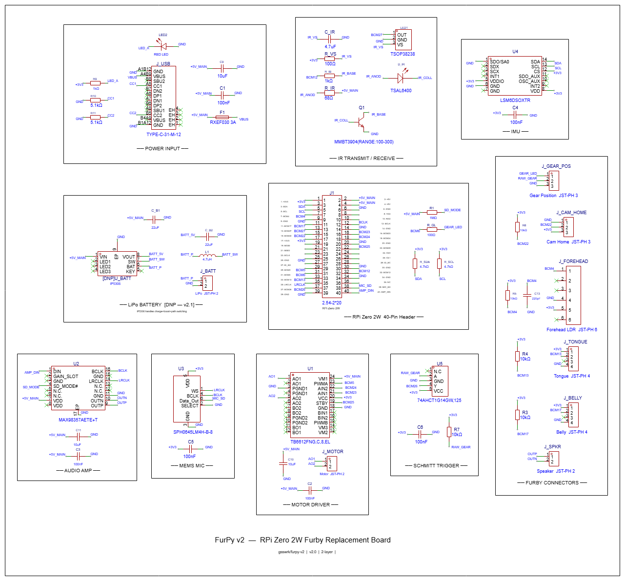
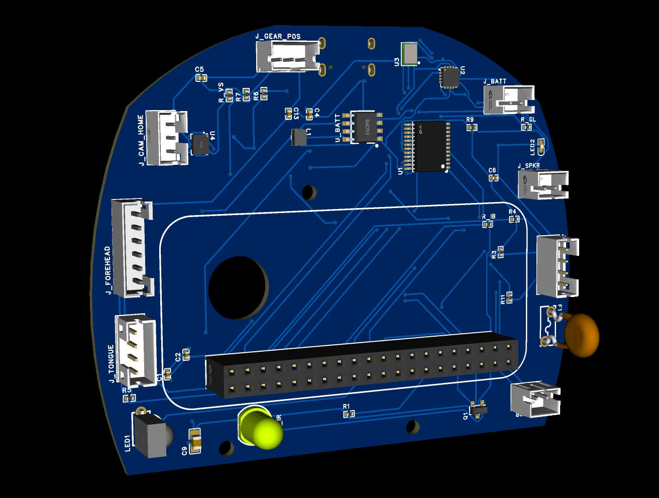
The schematic is complete in EasyEDA Pro, ERC clean. The PCB layout is complete, 84.6x68.3mm with a custom Furby-shaped board outline.
Drag to rotate, scroll to zoom. On iPhone, tap and hold the AR button to open in AR Quick Look.
What is not done yet: the board has not been ordered. Hardware has not been validated on a physical unit. The software stack beyond individual subsystem test scripts is not written. There is a lot of real work left between “PCB layout complete” and “this thing actually works in a Furby.”
The current checklist looks like this:
- SPC81A port map decoded from Dave Hampton’s 1998 source
- All sensors and actuators mapped to GPIO
- Schematic complete, ERC clean
- PCB layout complete
- Full BOM with verified LCSC numbers
- Order from JLCPCB
- Hardware validation on physical board
- HAL and firmware (motor, audio, mic, IMU, IR)
- Voice pipeline (openWakeWord, Whisper, piper-tts)
- Behavior scripting system
- Install guide
The Open Platform Part
The thing I keep coming back to when people ask what FurPy is actually for: it is a platform, not a product. The hardware abstraction layer exposes every piece of original Furby hardware as a Python API. Drop a script into /home/pi/furpy/behaviors/ and it loads at startup:
1
2
3
4
5
6
7
8
9
10
import furpy

@furpy.on("belly_press")
def on_belly(event):
    furpy.motor.move_to("surprised")
    furpy.speak("Hey, watch it!")

@furpy.on("ir_receive")
def on_ir(payload):
    furpy.ir.send({"reply": "hello back"})
The goal is that you should not have to understand the cam mechanism or the gear sensor timing loop to make the Furby do something new. You just write the behavior.
Repo is at github.com/gsswrk/furpy-v2. More updates when the boards come back from fab.